Views: 0 Author: Site Editor Publish Time: 2026-07-17 Origin: Site


Specifying the wrong machinery drive component leads to premature wear, sudden drive stalling, and costly production downtime. Industrial facilities operate under intense demands, making careful equipment selection paramount. Drive conditions—such as severe shock loads, intense ambient heat, and specific pulley sizes—dictate a tailored approach. A one-size-fits-all approach to equipment simply fails in modern operational environments. When you ignore these operational variables, you risk catastrophic system failures, damaged rotating equipment, and unsafe working conditions. We provide an evidence-based framework for evaluating your specific drive conditions in this comprehensive guide. You will learn how to accurately evaluate baseline requirements and shortlist the exact profile required for optimal performance. We will walk you through essential parameters, environmental hazards, and implementation risks to ensure your machinery runs smoothly for years.
Selecting a rubber V belt requires baseline data: design power, RPM, center distance, and environmental hazards.
Classic V belts offer broad utility, while narrow V belts solve high-power, space-constrained requirements.
Understanding peak operating conditions (e.g., stalling, high heat) determines whether to specify a wrapped V belt or a raw-edge cogged variant.
Proper installation tension and pulley alignment are as critical to the belt's lifecycle as the material composition itself.
To successfully choose a drive component, you must first gather baseline operational data. You cannot simply guess these mechanical parameters. Precision at this stage prevents catastrophic equipment failure later. We strongly recommend documenting four primary categories of engineering data before making any selection.
Load and Power Demands: You must calculate the exact design power. Do this by multiplying the motor's rated horsepower by a specific service factor. Service factors account for the crucial difference between continuous operation and intermittent use. A heavy rock crusher requires a much higher service factor than a centrifugal water pump. This initial calculation ensures the power transmission belt handles peak operational loads without snapping.
Speed and Ratios: Identify the exact revolutions per minute (RPM) of both the drive and driven pulleys. These numbers help you determine the required speed ratio. The speed ratio directly influences the appropriate belt length and profile. Accurate RPM data prevents component slipping and guarantees efficient energy transfer.
Spatial Constraints: Always measure the center distance between operating shafts. You must also measure the exact pulley diameters. Compact drives often utilize exceptionally small sheaves. These tight spaces limit the thickness and flexibility of the components you can install. A thick profile cracks quickly if forced over an undersized sheave.
Environmental Factors: Operational surroundings degrade rubber materials rapidly. Document the maximum ambient temperature around the operating machinery. Note any direct exposure to petroleum-based oils or harsh chemical solvents. You must also check for abrasive dust in the surrounding air. Airborne dust acts like coarse sandpaper against moving elastomeric parts.
Common Mistakes:
Relying solely on motor nameplate horsepower instead of calculating real-world design power.
Ignoring ambient heat buildup inside enclosed machinery safety guards.
Measuring worn pulleys instead of consulting original equipment specifications.
Machinery manufacturers utilize several standard profiles to solve different engineering challenges. Each specific profile has distinct mechanical advantages. You must match the profile geometry directly to your gathered baseline data.
The classic V belt represents the most widely recognized standard in the manufacturing industry. It features a traditional wedge shape.
Best for: Standard, continuous-duty applications. They work perfectly for fractional horsepower motors and moderate power requirements.
Pros/Cons: They are highly forgiving of slight shaft misalignments. However, they require more physical operating space. They also deliver lower power transmission density compared to modern alternatives.
Engineers developed the narrow V belt to maximize power transfer in exceedingly tight spaces. It features a deeper, steeper wedge profile.
Best for: Heavy-duty industrial applications. We specify them when equipment requires massive power transfer within a highly compact drive envelope.
Pros/Cons: The higher wedge angle provides exceptionally greater grip and heavy load capacity. Conversely, it requires specific narrow-profile sheaves. You must also ensure precise laser alignment during installation.
The exterior construction significantly affects dynamic performance during sudden operational changes.
Wrapped V Belt: A tough fabric cover encloses the internal core. This cover allows for safe momentary slippage without catastrophic failure. We highly recommend a wrapped V belt for drives involving mechanical clutching mechanisms. They also excel where sudden shock loads frequently occur.
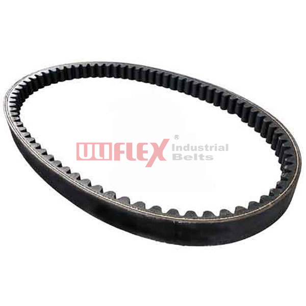
Raw Edge/Cogged: These designs lack an external fabric cover. Exposed interior rubber grips the sheave side-walls fiercely. The molded cogs allow the material to bend easily over much smaller pulleys. They also dissipate internal heat effectively. However, they are far less tolerant of drive stalling or heavy clutching.
Profile Comparison Chart
Belt Profile | Primary Advantage | Ideal Application |
|---|---|---|
Classic | Forgiving of minor misalignment | Standard continuous-duty fans |
Narrow | High power transmission density | Compact heavy machinery |
Wrapped | Safe momentary operational slippage | Clutched drives and conveyors |
Raw Edge Cogged | Rapid heat dissipation and high grip | High-speed small-pulley drives |
Real-world operations rarely mirror perfect laboratory settings. Severe environmental conditions destroy incorrectly specified parts within days. You must adapt your selection to survive these hostile environments. Choosing a specialized rubber V belt prevents unexpected mechanical breakdowns.
High-Shock and Pulsating Loads: Heavy equipment generates massive structural vibration. Rock crushers and industrial air compressors experience extreme load spikes. These violent spikes cause individual belts to violently whip. They often flip over entirely inside the pulley grooves. To prevent this, you require banded (joined) components. A high-strength tie-band connects multiple profiles across the top. This rigid band forces all sections to work together smoothly.
Stalled Drive Scenarios: Engineering reality dictates we plan for failure states. Sometimes a conveyor jams, causing the driven shaft to stall completely. The electric motor usually continues turning. A standard high-grip profile will permanently stretch or burn under this intense friction. A wrapped profile is often preferred here. The fabric cover permits safe, momentary slippage. It buys precious seconds until the thermal overload relay trips the motor off.
Extreme Thermal Environments: Ambient heat degrades elastomers rapidly. Standard natural rubber breaks down at temperatures above 140°F (60°C). Once it bakes, the material hardens and cracks over the sheaves. Drives located in high-heat areas require advanced materials. You must specify EPDM or a specially compounded synthetic rubber. These engineered materials resist thermal degradation and prevent premature snapping.
Best Practices for Severe Conditions:
Inspect machinery safety guards to ensure adequate ventilation for heat dissipation.
Install banded profiles on any machine experiencing frequent pulsating load variations.
Specify EPDM synthetic compounds if ambient operational temperatures regularly exceed 140°F.
A perfectly specified industrial rubber belt fails instantly if installed poorly. Execution matters just as much as engineering data. Maintenance technicians must follow strict installation protocols to guarantee the expected component lifecycle.
The Risk of Over-Tensioning: Novice mechanics often over-tighten drives to compensate for audible slippage. This practice causes immense structural damage. Excessive tension pulls violently against the shaft bearings. It destroys bearing seals and causes rapid system overheating. Furthermore, over-tensioning stretches the internal tensile cords beyond their natural elastic recovery point. Use a sonic tension meter or a calibrated deflection gauge to set proper tension accurately.
Pulley Sheave Wear: Sheaves wear out naturally over time. Abrasive dust and friction grind away the metal sidewalls. The grooves become dished out or excessively wide. Even premium components fail quickly if installed on worn pulleys. The new profile drops too low into the metal groove. It loses critical edge contact and slips immediately. Sheave groove inspection using a physical template gauge is absolutely mandatory before any replacement.
Matching Sets: Multi-groove drives require perfectly matched components. They must share the operational load equally. You must purchase sets derived from the exact same production batch. This guarantees identical length and uniform elasticity. Mixing old and new components guarantees unequal tension. The newer, tighter profile takes the entire mechanical load and snaps prematurely.
Finalizing your selection requires structural logic. You should evaluate long-term performance gains rather than just initial fitment. Following a systematic procurement process ensures your facility maximizes operational uptime.
Performance Lifecycle Evaluation: Evaluate the long-term operational impact. A premium raw-edge cogged profile yields substantial facility energy savings. It bends easier, wasting less motor energy on internal friction. It also provides longer replacement intervals compared to a standard wrapped profile. Evaluate these lifecycle benefits when reviewing your facility's preventative maintenance schedules.
Cross-Referencing OEM Specs: Never guess an equipment upgrade path. Always verify the manufacturer's original engineering manual for specific service factors. Upgrading from a classic profile to a narrow profile requires complete sheave replacement. You cannot mix profile geometries. Ensure your engineering team verifies the exact shaft dimensions before ordering new sheaves.
Consulting the Supplier: Leverage external engineering expertise. Bring your thoroughly documented drive data to a specialized technical distributor. Share your exact horsepower, RPM, center distance, and environmental hazards. They will run a computerized drive design verification. This advanced software confirms your shortlisted choice mathematically. It eliminates human error from the complex calculation process.
Selecting the right machinery drive component is an exact science. It is a strict exercise in matching power transmission requirements against specific environmental and spatial constraints. Precision guarantees longevity and efficiency. Do not automatically replace a failed component with an identical model without diagnosing the root cause. The unique drive conditions may dictate an immediate upgrade to a different profile or a specialized synthetic compound. Stop relying on guesswork for your machinery maintenance. Contact an application engineering team today and share your exact specifications for a verified, engineered recommendation.
A: Yes. If the drive stalls and the motor continues running, localized friction generates severe heat. This extreme friction can permanently degrade the internal tensile cords. It ultimately causes irreversible stretch or snaps the component entirely.
A: A toothed (cogged) belt is generally better for high-speed drives utilizing small pulleys. The molded cogs allow for much greater flexibility. They also provide superior heat dissipation. These factors make them significantly more efficient than regular wrapped options under high-speed conditions.
A: Measure the top width and the depth of the profile using reliable digital calipers. Combine these exact dimensions with the outside circumference measurement. Use a flexible tape measure for the circumference. Cross-reference these three numbers against a standard manufacturer's dimension chart to identify the exact profile.