Views: 0 Author: Site Editor Publish Time: 2026-08-01 Origin: Site


In synchronous conveying and precise indexing, standard friction belts cannot guarantee exact part placement. A minor slip translates directly to catastrophic automated assembly failures. High-speed automation demands absolute accuracy at every station. Specifying a timing belt equipped with custom attachments requires balancing payload geometry alongside underlying belt flexibility. An incorrectly designed cleat or an incompatible base material inevitably leads to premature delamination, track drift, or severe drive system jamming. These preventable failures halt production lines and cause immense operational frustration. This article provides engineers and procurement teams an evaluation-based framework for choosing correct cleat designs, exact tooth profiles, and reliable manufacturing specifications. We want you to confidently select a dependable positioning belt without over-engineering your drive solution.
Cleat geometry must be matched directly to the part being conveyed (pushing, nesting, or dividing) while accounting for the increased stiffness added to the base belt.
Welding cleats onto a polyurethane (PU) belt alters the minimum pulley diameter (MPD) requirements; failing to adjust pulley size is the leading cause of weld fatigue.
Standardizing the tooth profile (e.g., AT vs. T series) based on torque and speed constraints is just as critical as the top-cover cleat design.
Accurate CAD modeling and realistic tolerance expectations for welded profiles are mandatory to prevent physical interference during machine operation.
You will reach a performance ceiling using standard flat belts. Standard synchronous systems also struggle under specific operational constraints. Engineers must identify the exact threshold where friction-based conveying fails. High-speed indexing requires rapid starts and stops. Vertical inclines demand structural support to prevent product rollback. Exact-pitch placement demands rigid adherence to spatial coordinates.
Friction belts inevitably slip during rapid acceleration. Standard synchronous belts transfer rotary motion smoothly but offer no mechanism to secure discrete items along the belt surface. When a product must arrive at an assembly station at a precise millisecond, friction alone proves inadequate.
A welded profile timing belt solves this dilemma. It locks the product strictly to the belt pitch. You can visualize this setup as a continuous linear gear. Automated robotics, packaging equipment, and assembly lines rely on this rigid spacing. The base belt maintains the mechanical timing, and the attached profiles secure the physical payload. They move as one synchronized unit.
There is an initial investment difference. Profiled options require specialized manufacturing processes. However, you must weigh this upfront expense against ongoing operational waste. Misaligned products cause jams, ruin components, and trigger frequent machine faults. Investing in precise mechanical control drastically reduces long-term scrap rates. You gain reliable, uninterrupted production.
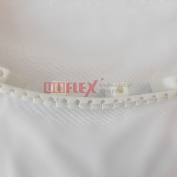
Cleat selection defines the entire system geometry. You must match the profile shape directly to the product being transported. A profiled timing belt accommodates hundreds of different shapes. However, they generally fall into three primary categories.
Pushers act as moving backstops. They propel items forward along a supporting guide rail or slide bed. They work best for heavy, stable items requiring linear acceleration. Cardboard boxes, solid metal blocks, and rigid trays fit this category perfectly.
Pushers carry a significant design constraint. They require thicker base dimensions to absorb the pushing force without bending backward. This added thickness makes the belt highly susceptible to bending stress over pulleys. The thick base creates a rigid zone. You must increase pulley diameters to compensate for this rigidity.
Nests cradle the product entirely. They form custom cavities matching the product footprint. They work best for fragile, cylindrical, or highly irregular components needing multi-point support. Glass vials, delicate electronic housings, and cosmetic tubes require nesting to prevent rolling or surface damage.
Nesting introduces distinct manufacturing constraints. These designs often require CNC-machined profiles. Precise pitch spacing remains non-negotiable. If the nest spacing shifts by a fraction of a millimeter, automated pick-and-place robots will crash into the product.
Dividers create separate compartments along the belt surface. They work best for bulk material handling or spacing loose components evenly. You often see them moving granular materials up inclines or keeping loose parts separated before a sorting station.
These applications frequently require taller profiles. Taller flights introduce a unique challenge. They must navigate pulleys without snapping off at the base. To solve this, engineers utilize specific undercut designs or relieved bases. This allows the tall flight to flex outward as the belt curves around the pulley.
Cleat Category | Ideal Application | Primary Advantage | Key Design Constraint |
|---|---|---|---|
Pushers & Lugs | Heavy, rigid items (boxes, metal parts) | High structural strength for linear propulsion | Requires larger pulley diameters due to base rigidity |
Nests & Pockets | Fragile or cylindrical items (vials, tubes) | Total product immobilization and protection | Strict spacing tolerances; often requires CNC machining |
Dividers & Flights | Bulk materials, loose part sorting | Maximum volume capacity on inclines | Needs base undercuts to navigate pulleys safely |
Attaching a custom profile alters the fundamental dynamics of the base belt. You cannot design the top cover independently from the drive surface. A successful system requires synergy between the tooth geometry and the attached payload.
Tooth profile dictates the underlying backbone strength. Standard trapezoidal shapes, like the T-series, provide excellent general positioning. They are easy to manufacture and highly available. However, they struggle under sudden shock loads. For heavier payloads, you should evaluate high-torque AT-series or curvilinear HTD profiles. An AT-series belt offers superior tooth shear strength. This strength prevents the belt from ratcheting when pushing heavy lugs.
Engineers consistently overlook the Minimum Pulley Diameter (MPD) rule. Welded attachments stiffen the belt significantly. A standard PU profile belt flexes easily around a small pulley. Once you weld a thick cleat onto its back, you create a rigid section. Forcing this rigid section around a small pulley creates massive bending stress at the weld seam.
You must calculate the new MPD based on the cleat base thickness. A thicker base demands a proportionally larger pulley. Failing to adjust pulley size remains the leading cause of premature weld fatigue. The constant stretching and compressing at the hinge point will tear the profile completely off the belt.
Cleat placement strategy also matters. You should ideally position cleats directly over the belt tooth, not over the root. The belt root serves as the primary flex zone during rotation. Placing a rigid weld directly over this flex zone restricts articulation. Centering the profile over the tooth maintains natural flexibility. It distributes shear forces safely downward into the pulley groove.
Joining two pieces of polyurethane creates a new structural reality. The bond will never possess the exact tensile strength of virgin material. Understanding welding techniques helps engineers mitigate inevitable failure risks.
Manufacturers generally use thermal bonding or high-frequency friction welding. Standard thermal bonding uses focused heat to melt both surfaces before pressing them together. It works well for standard loads. High-frequency or friction welding uses rapid vibration to generate internal heat. This technique forces the molecular chains to fuse deeply. It produces higher structural integrity for welded cleats enduring heavy shock loads.
We must address the skeptical engineer directly. The weld seam always represents the primary failure point. You cannot eliminate this reality, but you can design around it. Engineers mitigate shear stress by incorporating specific geometric features into the cleat base.
Consider these critical structural mitigations:
Undercuts: Removing material from the center of the cleat base allows the edges to flex independently over pulleys.
Gussets: Adding triangular side supports strengthens tall pushers against backward bending forces.
Relieved Bases: Tapering the front and rear edges of the weld zone reduces peeling forces during articulation.
Material Matching: Ensuring the cleat durometer closely matches the base belt durometer prevents uneven stress distribution.
Tolerance accumulation presents another hidden risk. Thermal processes alter material dimensions. When a manufacturer applies heat to weld 50 separate profiles, the base PU material experiences micro-shrinkage. A single millimeter of shrinkage over a long span completely misaligns the final pitch. You must set realistic expectations for pitch tolerances after the welding process. Consult your supplier about their pre-tensioning and post-weld stabilization procedures.
System reliability depends entirely on accurate environmental definitions and precise digital modeling. You cannot specify a cleated timing belt based solely on payload weight.
First, define the operating environment clearly. Create a comprehensive checklist for your supplier. You must detail chemical exposures. Oil, grease, and cleaning agents degrade standard urethanes rapidly. Washdown requirements dictate strict hygiene standards and water resistance. Operating temperature thresholds influence material durometer. High heat softens cleats, while freezing environments make them brittle and prone to shattering.
Second, emphasize strict digital verification. Acquiring accurate 3D CAD profiles from your manufacturer is mandatory. Do this before finalizing your machine design. Standard 2D drawings often obscure complex collision risks. You need exact 3D models to verify clearances. Run full kinematic simulations. Check for interference fits around guide rails, return paths, and sensor brackets. Ensure the cleats clear structural supports as they fan out over the pulleys.
Finally, adopt a phased prototyping strategy. Do not invest immediately in custom injection-molded or multi-axis CNC machined profiles. Start with standardized, off-the-shelf cleat shapes. Use them to validate your proof-of-concept. Test the linear acceleration, verify the pulley diameters, and confirm the general spacing. Once the fundamental mechanics prove stable, you can confidently invest in highly customized shapes.
A successful positioning system requires true holistic design. You must continuously balance complex part geometry against dynamic flex requirements. An over-engineered heavy cleat destroys belt flexibility, while an under-engineered profile snaps under payload strain. Recognize that welding permanently alters pulley diameter formulas. Remember that placement over the tooth preserves the critical root flex zone.
Your next step requires data compilation. Gather your exact payload dimensions, maximum speed constraints, and environmental checklists. Document the chemical and temperature exposures. Reach out to an application engineer with these details to request precise CAD models. Initiate a formal design review immediately to validate your initial proof-of-concept.
A: Overmolded belts are cast in a single mold, making the base and cleats one continuous piece. This offers superior bond strength but requires expensive tooling and long lead times. Welded versions bond individual profiles onto an existing base belt. They offer rapid prototyping, lower upfront costs, and endless shape customization.
A: Adding attachments completely disrupts flat back-bending. Backside idlers are generally prohibited because they crush the profiles. If you must use a tensioner on the back side, you must utilize specially designed grooved rollers. These rollers allow the tall attachments to pass through freely without making physical contact.
A: Field repairs are generally unreliable. Once a profile tears away, it damages the underlying base material. Attempting to re-weld a new piece onto compromised polyurethane yields weak bonds. In heavy industrial applications, full belt replacement remains the standard procedure to guarantee continued precision.
A: Standard industry baseline expectations for linear spacing along the belt pitch generally fall within ±0.5mm to ±1.0mm per profile. Perpendicular alignment across the width typically holds a tolerance of ±0.5 degrees. Exact tolerances vary based on base material shrinkage and the specific welding method utilized.